1. Introduction
Why is a site assessment required?
A site assessment needs to be done in advance before each event to ensure that the venue is suitable without any interferences for the technology and equipment.
2. Requirements
The following must be fulfilled before proceeding with the rest of the manual.
You have the required hardware and software that includes the following:
Hardware
- 1 x laptop
- 5 x Axis nodes
- 1 x USB A or USB C dongle
- 4 x Axis leg straps with node holders
- 1 x Axis spine strap with node holder
Software
- AXIS Control Center (test will be done within the control center)
Others
- Ensure all devices are up to date
- Laptop is fully charged and able to be mobile for testing
- AXIS nodes are charged for at least 2 hours
- AXIS nodes are paired
- 1 x person donning Axis (5 nodes with straps)
- Spine
- Both thighs
- Both calves
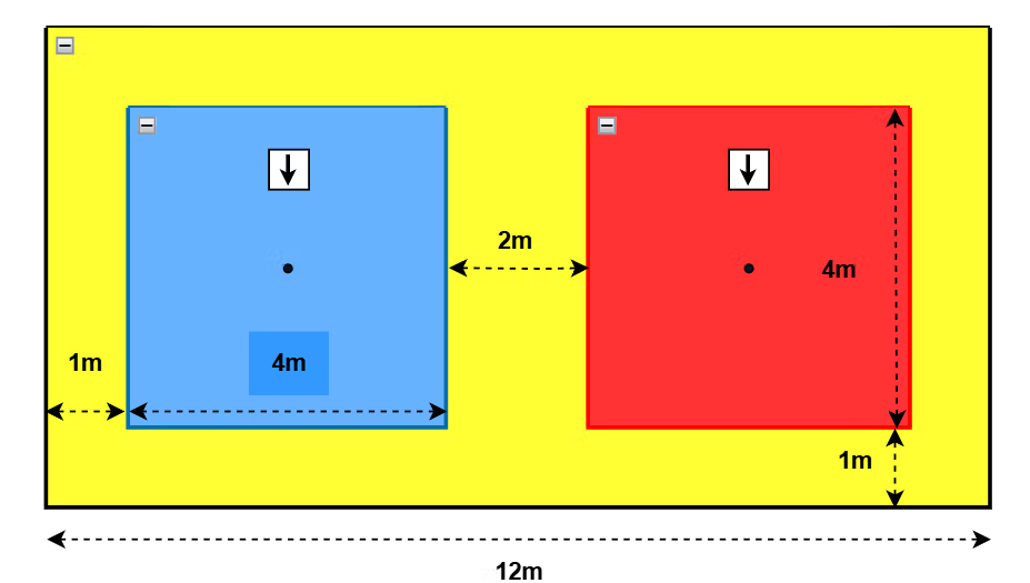
- Confirm location/position of the Field of Play (FOP)
*You may refer to the VTKD manual for the full set-up of all VTKD equipment.
3. Precaution
There should not be any metal structure nor electrical cabling within the whole FOP (including outer safety boundary)
4. Site assessment steps
Calibration
- Strap on AXIS with straps.
- Check AXIS Channel assignment (any of the channels can be used as long as they are on the same channel, e.g: channel 1).
- Take a step back, 1m from the middle of your FOP (as shown in the image below).
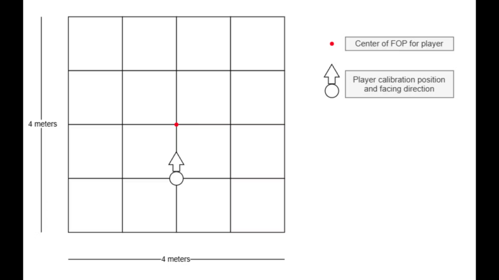
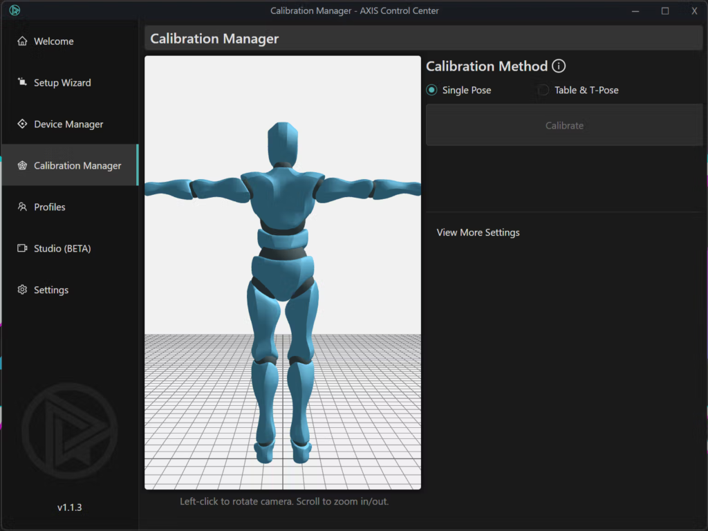
- Calibrate AXIS in AXIS Control Center (AXIS CC) under the “Calibration Manager” tab.
- Do not readjust the strap position throughout the test.
Moving within the FOP to check for interference
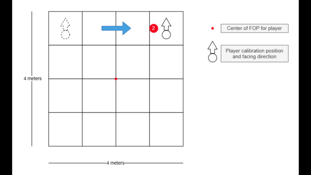
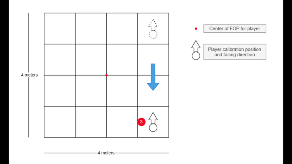
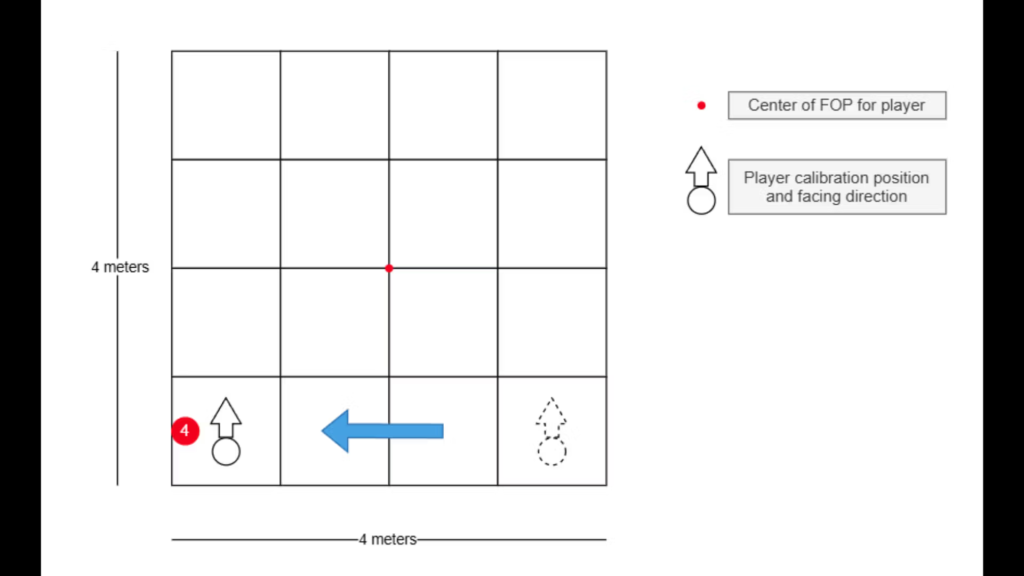
- Facing the same forward direction throughout the test, walk towards the position number shown in red from the image below.
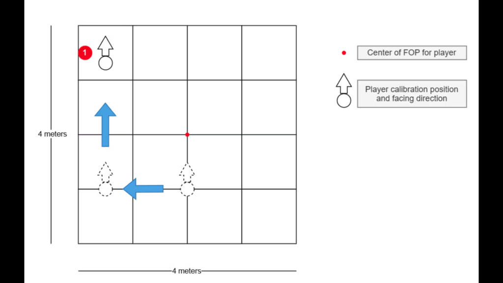
- Stand on the spot for 5-10 seconds and observe for any drift* of your body and limbs on the AXIS CC. *(A drift is when your body or limb turns to any direction while you are standing still on the spot)
- Acceptable range: If a drift is observed to be approximately less than 10 degrees.
- Unacceptable range: If a drift is observed to be approximately more than 10 degrees.
- (You may refer to the appendix page at the bottom of this document here)
- For record, save a screenshot of your Axis CC and rename the file as: ‘<fop>_<color>_front_left.png’ (e.g: FOP_A_blue_front_left.png)
- Repeat steps no.1 to no.3 for all other positions and in both the blue and red field of play (FOP). Refer to images below for testing positions.
- Front right (FOP_A_blue_front_right.png)
- Back right (FOP_A_blue_back_right.png)
- Back left (FOP_A_blue_back_left.png)
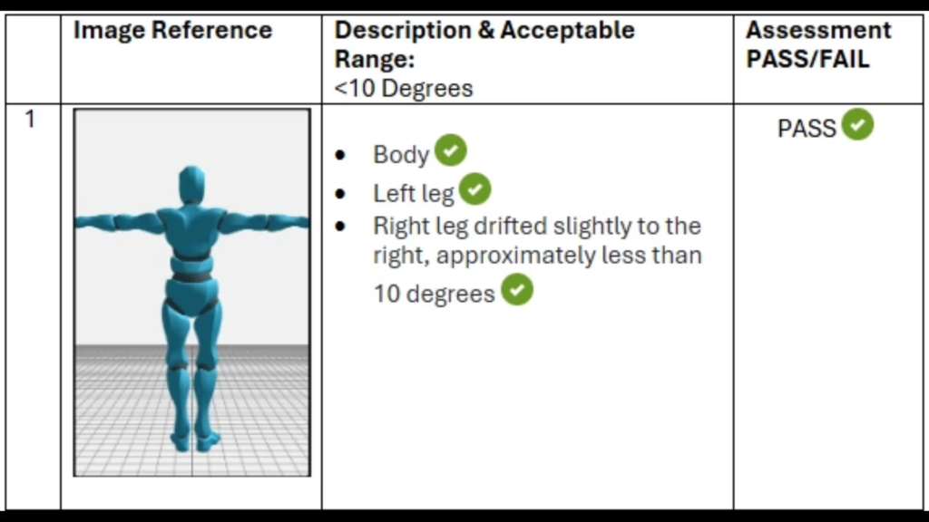
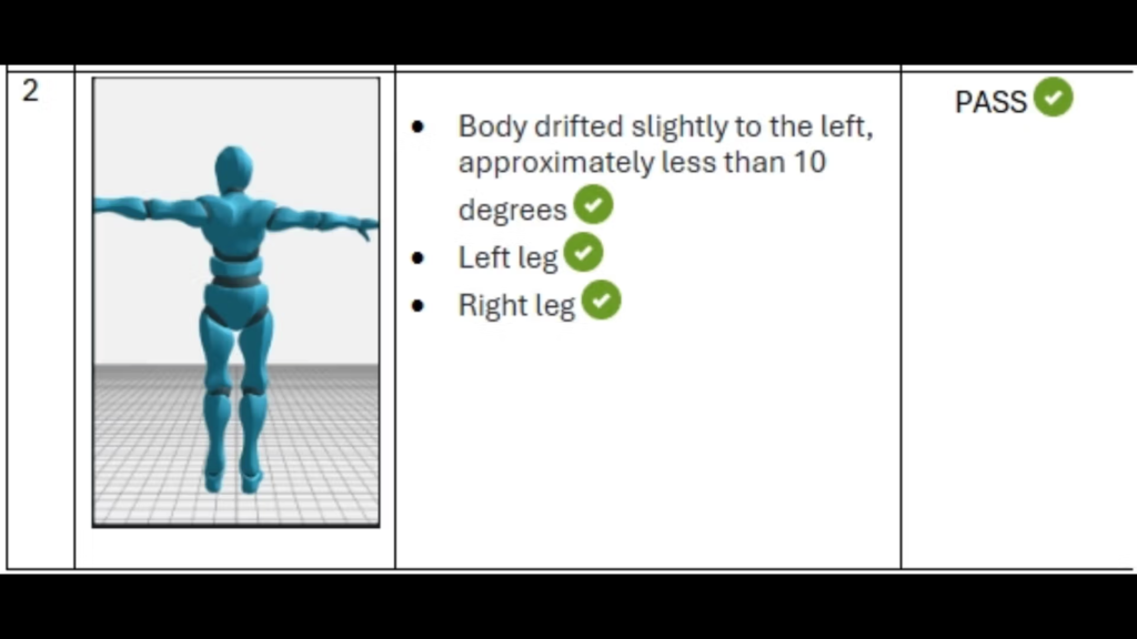
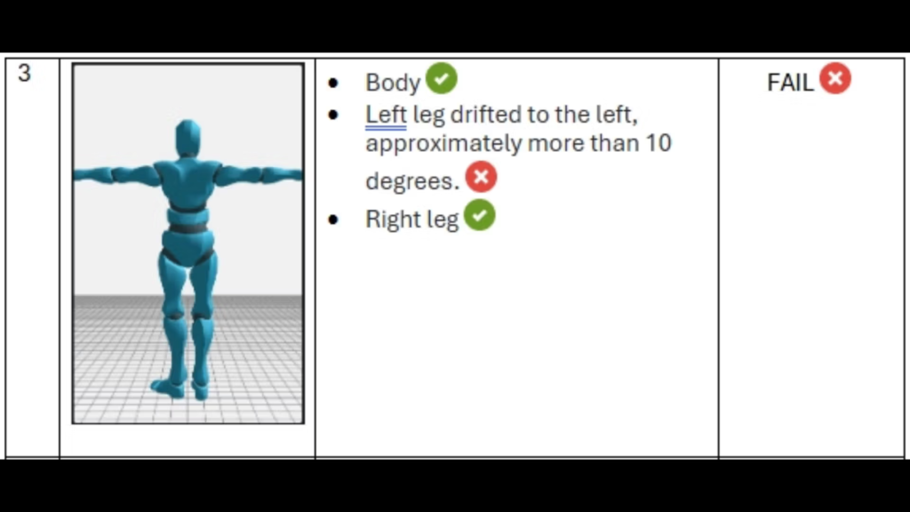
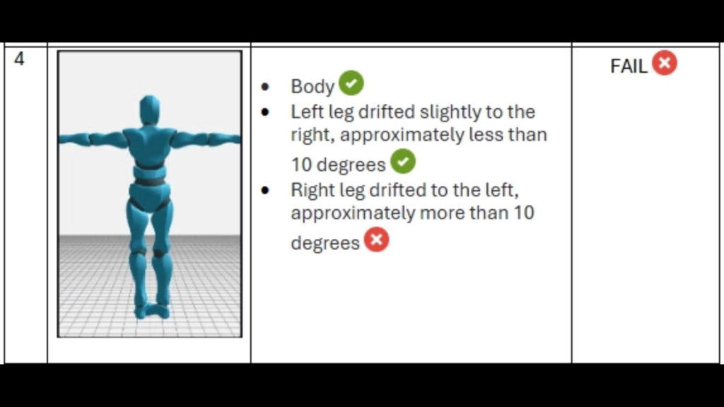
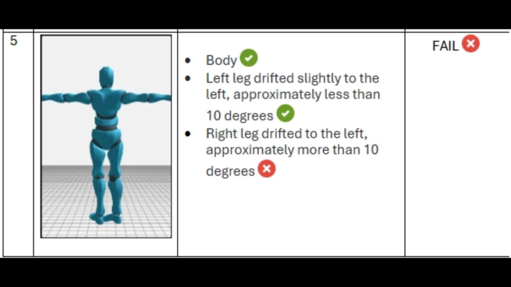
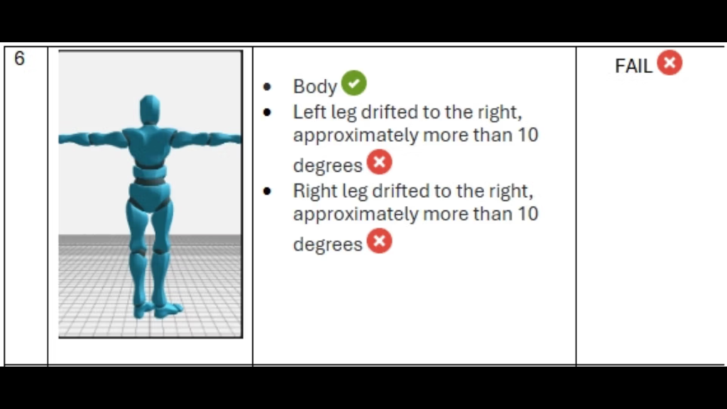
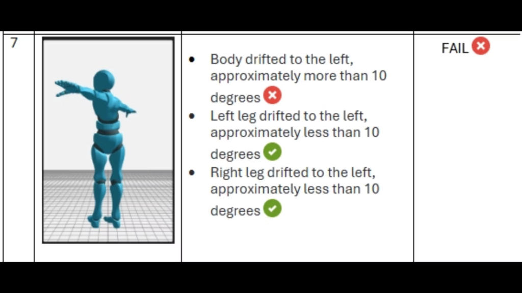
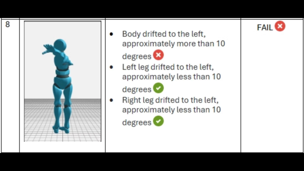
5. Appendix
Here in the appendix, the images below will portray examples of acceptable and unacceptable tracking behaviour.